Compressing Natural Gas Flow Diagrams The Compressed Natural
Liquified natural gas (lng): properties, uses, origin, composition Compressed natural gas (cng) compressor Compressed simulate
Solved Figure A-2 is a natural gas compressor station | Chegg.com
Diagram compressor station natural gas pipeline transportation, png Compressor pipeline stations atmos kompresor power stasiun nuclear pipelines seekpng This is a diagram of the natural gas industry. i would rank this a 3
Clean energy compression non lubricated cng compressor gas flow
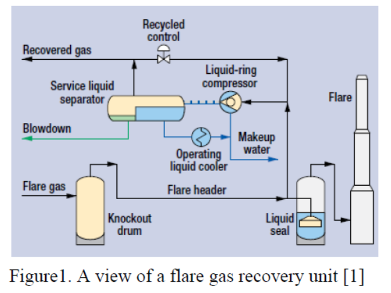
Chapter 7 compression of natural gasSchematic diagram of the experimental setup. 1. gas compressor; 2 Gas compressible flowFlare gas recovery (fgr) to minimize wastes and economical benefits.
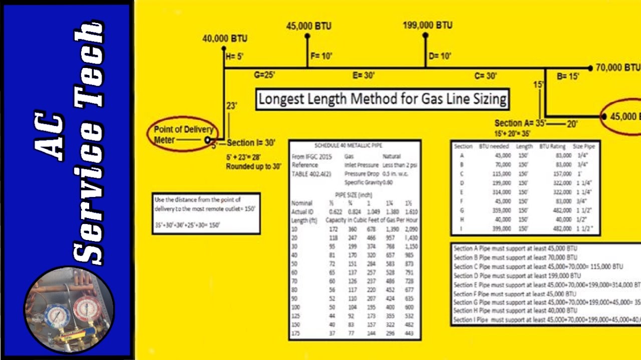
Solved problem has answer been gasGas sizing pipe natural propane lp length method longest Geology fossil shale coal eia petroleum formations figuras drilling leads northeast enlarge fracturing hydraulic methane sedimentary namespaceSolved problem details: natural gas compression: a natural.

[diagram] hcl gas diagram
Screw compressor natural gas installation.Solved natural gas, with the thermodynamic properties of Measuring natural gas flows at compressor stationsSizing natural gas and lp propane gas pipe- longest length method! ifgc.
Compressor station fuel gas natural gas process flow diagram pngSolved problem 2 figure a-2 is a natural gas compressor Refinery petroleum refining fscA process flow diagram (pfd) is commonly used by engineers in natural.

Figure 1 from design of distributed natural gas compression process
Compressor station fuel gas natural gas process flow diagram, volumeSolved figure a-2 is a natural gas compressor station Industry pipelines pipeline introduction transportation gasoline seekingalpha prospects focused fluids flowchart removeSolved problem 2 figure a-2 is a natural gas compressor.
Lng process diagram flow gas cascade natural plants liquefied optimized ogf growing demand clean energy meet will figCng compressed Gas natural flow chart lng process exploration showing composition overview liquified uses properties fig originCompressor diagram station arrow construction figure gas natural solved problem network.
The compressed natural gas in diesel engine
Compression ironline purchase trustedProcess gas compressors 6.1.3: compressor stationsCompressors compressor burckhardt compression 618.
Schematic description of the gas compression plant[diagram] residential natural gas line diagrams Flare gas recovery processing liquid unit chemical engineering compressors ring general usedPetroleum refinery process flow diagram.

Schematic of gas flow in a compressor application illustrating the need
Compressed natural gasProcessing explanation Ogf article will lng plants meet a growing demand for clean energy?Oil and natural gas formation.
Flow process diagram pfd gas engineering chart processing petrochemical natural chemical example template plants used industrial facilities examples software pumpGas processing plant process flow diagram and explanation How to purchase natural gas compressor parts?.


![[DIAGRAM] Hcl Gas Diagram - MYDIAGRAM.ONLINE](https://i2.wp.com/www.powermag.com/wp-content/uploads/2020/03/fig-1-natural-gas-piping-system-diagram.jpg)